R7 meters
 print
print

I.Overview
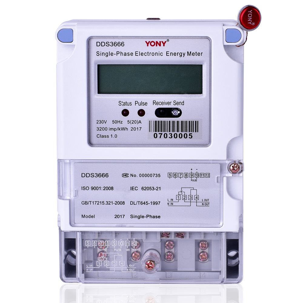
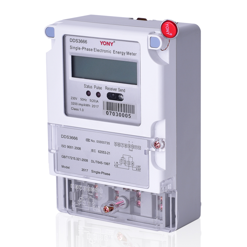
DDS3666 Single-Phase Electronic Energy Meter adopts the most advanced solid-state integrated circuit technology with ultralow power loss and SMT technology. It is used to measure alternating current single phase active energy with frequency of 50Hz.The performance index confirms to the technological requirements for the single phase static energy meter according to IEC62053-21-2003 , GB/T17215.321-2008 “AC Static Active Energy Meter (Class1 and Class2)” and the technical index for static single phase energy meter in DL/T 645-1997“ Multifunctional Energy Meter Communication Protocol”.
II. Function and Feature
1.Wide load range ; high accuracy , reliability and sensitivity; low power loss.
2. Bi-directional measuring, accurately measure the active energy of both forward and reverse power.
3.Passive pulse output interface with optocoupler isolation.
4. Infrared communication interface. Baud rate is fixed at 1200.
5. RS485. Baud rate is 1200, but it can be set at 600 ,1200,2400, 4800 or 9600.The meter collects data in a convenient and reliable way by connecting to a concentrator which communicates by GPRS.( This function is optional.)
6. Relay to control the switching on/off of the load. ( This function is optional.)
7. The meter uses LCD in a clearer display and nicer appearance.The total consumed energy is displayed in the top line, while the other items of constant,meter NO., voltage , current,power, power factor and frequency are displayed in the lower line in turns with an interval of5 second .
III. Specifications and Parameter
1.Specifications
|
type |
Class index |
Reference voltage Un |
Rated current |
|
DDS3666 |
Class 1 |
220V,230V |
3(9)A,5(20)A, 10(30)A, 10(40)A,15(60)A, 20(80)A, 30(90)A, 30(100)A,50(120)A |
2. Basic error (Ib is basic current,Imax is maximum current)
|
load current |
power factor |
elementary error(%) |
|
Class 1 |
||
|
0.05Ib |
1.0 |
±1.5 |
|
0.1Ib~Imax |
1.0 |
±1.0 |
|
0.1Ib |
0.5(lag) |
±1.5 |
|
0.8(lead) |
±1.5 |
|
|
0.2Ib~Imax |
0.5(lag) |
±1.0 |
|
0.8(lead) |
±1.0 |
3 Starting: when reference voltage, reference frequency and power factor is 1.0, the meter of class 1 under 0.4%Ib, the meter can start and do measurement normally.
4 No load running: the meter has anti-shunt running logic circuit. when voltage circuit plus 1.15 times reference voltage, and there is no current in current circuit, the test output of meter is supposed not to have more than one pulse.
5 Power consumption:≤1W(5VA)
6 Environment condition
standard working temperature:-25℃~70℃
limit of working temperature:-25℃~80℃
note: Special requirement of working temperature limit:-40℃~80℃
Working Principle
The measuring chip samples the voltage and current signals and converts them into pulse signals which are proportional to energy. The signals are transferred to MCU chip to do the accumulation measurement, and output in passive pulse with optocoupler isolation. MCU and exchange and communicate data with the outside world meanwhile.
V. Installation and Wiring
Configuration and Dimension
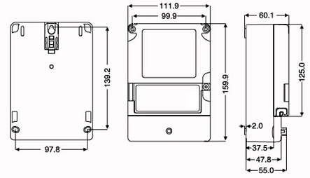
The meter is weather proof and its gasket material is IP 54 and it works well under the wet and high humidity.
Weight: About 0.6kg.
2.Wiring Diagram

VI. Transport and Storage
1 The meters should be transported and stored in accordance with the regulation of JB/T 9329-1999 the fundamental environment condition and test method of instrument and meter transport and storage, without any violent shocks in the process of transport and sealing off.
2 The meters should be stored in the original package, with a storage environment of a temperature-25℃~+80℃ and an average relative humidity ≤85% with no corrosive gas.
3 When stored in the warehouse, the meters should be placed on the rack with a stacking height of no more than6 cases. When unpacked, single packaged meters should be placed with a stacking height of no more than 10 pieces.
VII.Guarantee and After Sale Service
Under the condition of normal storage and transport, maintenance and employment from the customer part, we provide customers with free repair or exchange service if the product is found not confirming to requirements of product standards within guaranteed period after leaving factory.
VIII. Appendix
1. Communication Protocol
|
Sl.No. |
Data Items |
Data Pattern |
Read |
Write |
ID Code |
Data Length |
|
1 |
Total Energy |
XXXXXX.XX |
* |
|
9010 |
4 |
|
2 |
Meter Serial No. |
NNNNNNNNNNNN |
* |
* |
C032 |
6 |
|
3 |
Constant |
XXXXXX |
* |
|
C030 |
3 |
|
4 |
Relay Status |
On/Off status 000000YX X:0 order to switch on 1: order to switch off Y: 0 Actual switch on 1: Actual switch on |
* |
|
C029 |
1 |
|
5 |
Voltage |
XXX.X V |
* |
|
B611 |
2 |
|
6 |
Current |
XXX.XXX A |
* |
|
B621 |
3 |
|
7 |
Power |
XX.XXXX kW |
* |
|
B630 |
3 |
|
8 |
Power factor |
X.XXX |
* |
|
B650 |
2 |
|
9 |
Frequency |
XX.XX Hz |
* |
|
B664 |
2 |

Tel:+86-577-61662206 61662205
Fax:+86-577-61733361
Technical support:0577-61662201
Http://www.yoyatech.com
E-mail:sa2@yony.cc