Single-phase electronic meter

 print
print
1. Overview
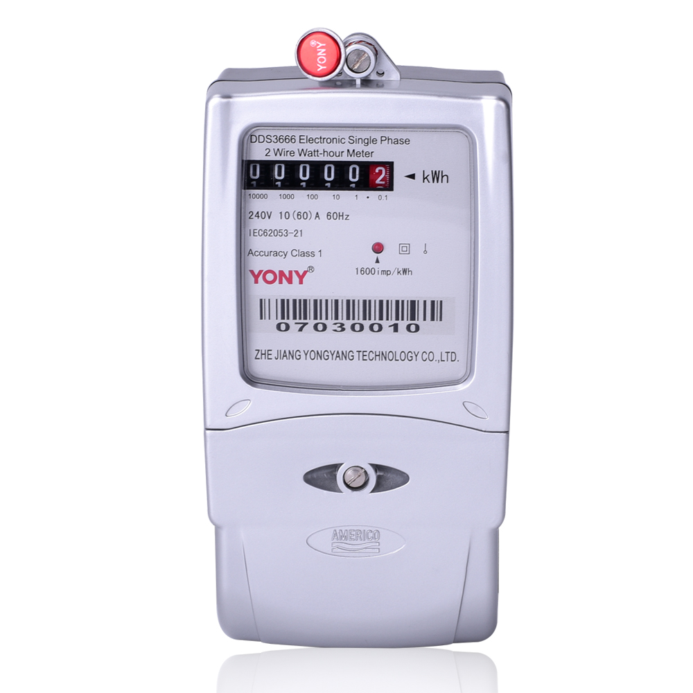
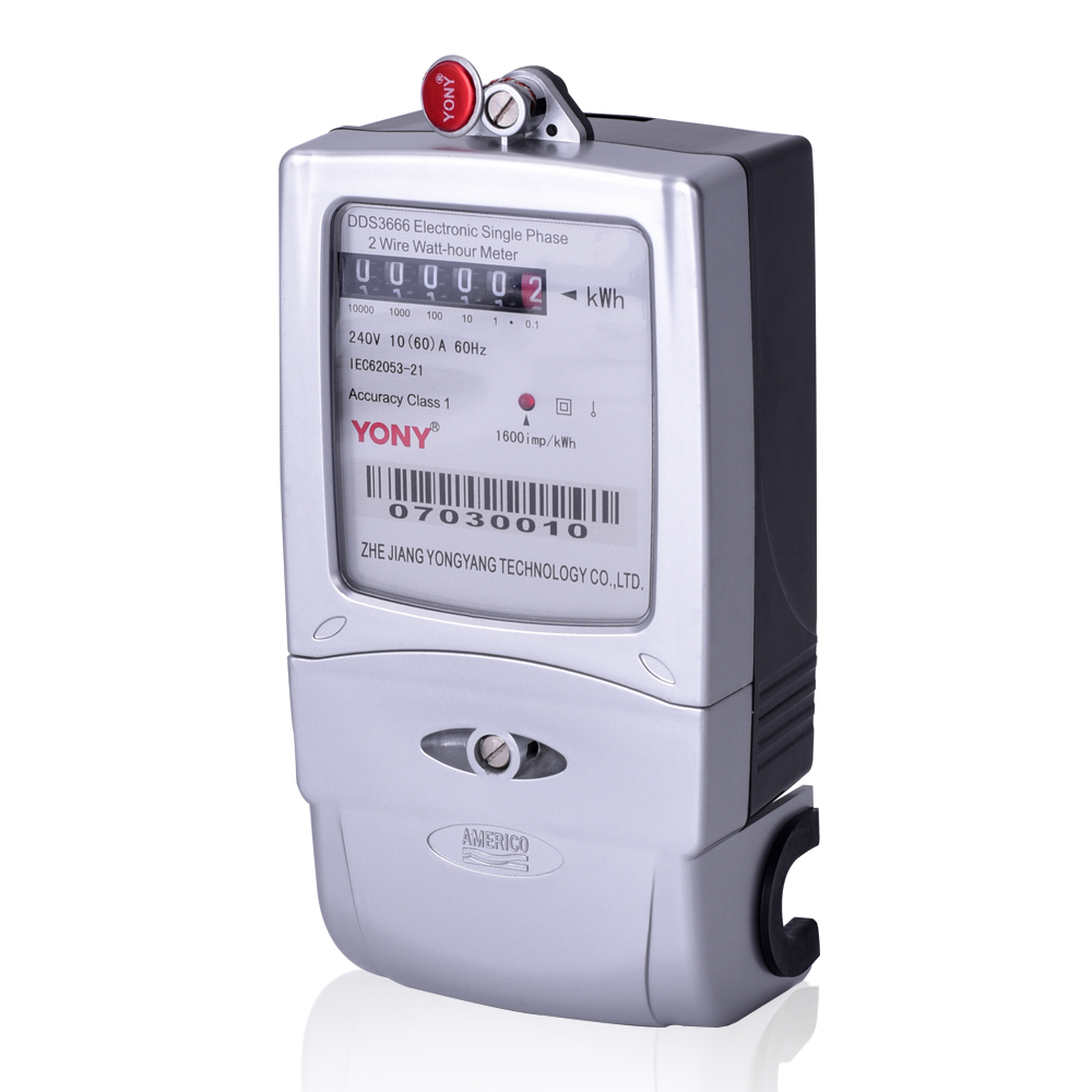
The model DDS3666 single-phase electronic watt-hour meter (hereinafter referred to as meters) is designed to measure active electric energy in a single-phase circuit with a 50Hz/60Hz reference frequency. It features excellent accuracy, reliability, stability and feasibility. It is integrated with internationally advanced ultralow power consumption LSIC, microprocessor and SMT technique. Using international brand long-life devices as its key parts increases its reliability and service life. The manufacture of the product complies with all technical indexes of IEC 62053-21 Class 1 and Class 2 Static AC Active Watt-hour Meter and GB/T17215.321-2008 Class1 and Class2 Static Alternating Current Active Energy Meter for the single-phase static watt-hour meter.
2. Main Specification
2.1 Specification
Voltage: 120V,220V, 230V, 240V.
Current: 1.5 (6) A, 5 (20) A, 5 (80) A, 5 (100) A, 10 (40) A, 15 (60) A, 20 (80) A, 30 (100) A.
Accuracy Class: 1.0 or 2.0.
Frequency:50Hz or 60Hz.
2.2 Basic Error
|
Current Value |
Power Factor |
Limit of Error (%) |
|
|
Class 1.0 |
Class 2.0 |
||
|
0.05Ib 0.1Ib~Imax |
1.0 |
±1.5 ±1.0 |
±2.5 ±2.0 |
|
0.1Ib |
0.5 (inductive) 0.8 (capacitive) |
±1.5 |
±2.5 - |
|
0.2Ib~Imax |
0.5 (inductive) 0.8 (capacitive) |
±1.0 |
±2.0 - |
2.2.1 Starting Current: Active£0.004Ib.
2.2.2 Creeping: When the voltage applied to the voltage circuit is 115% Un and the current in the current circuit is 0, the active pulse output of the meter is not more than 1 pulse.
3. Main Technical Indexes
3.1 Operating voltage range: 0.9Un~1.1Un, operating temperature range: -25℃~55℃.
3.2. Relative humidity: 25%~95%.
3.3 Power Consumption: Active power consumption in each phase of voltage circuit<1.5W, apparent power consumption<10VA.
3.4 The Terminal block is made of bakelite, and the meter cover and housing are made of polycarbonate, so the meter is excellent in mechanical strength and insulativity.
4.Main functions
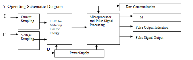
4.1 Energy measuring
The meter measures total active energy which includes both forward and reverse energy.
4.2 Output Interface
With optical coupler isolated active passive pulse output interface., the pulse indicator blinks
when there is a pulse.
4.3 Power Supply Indication
The light marked POWER will be continuously on to indicate there is power supply.
4.4 Display
The meter displays energy data by register
6. Installation and Connection
6.1 Physical Dimension Figure:

6.2 The meter has been lead sealed and proven qualified prior to delivery. Check the lead seal for any damage before installation. If it is ok, install the meter.
6.3 Install the meter in a dry and well-ventilated indoor place, fixing it in place with a hook and two screws. Install it in a cubicle to protect it from dirt and possible damages.
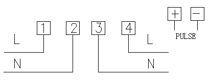
6.4 Connect the meter correctly as shown in the wiring diagram. It is recommended to use a copper wire or a copper connector as the lead-in wire to the terminal block. Tighten terminal screws to avoid being burnt down caused by heat of poor contact or thin lead wire.
6.5 The meter enters normal operating status after being connected as described above and powered on.
6.6 Wiring Diagram
7. Transportation and Storage
Do not subject the meter to violent shock during transportation and unpacking. Transport and store it in accordance with the requirements of Basic Enviromental Conditions and Test Methods for Transportation and Storage of Meters and Instruments (JB/T 9329-1999). Store meters packed in their original boxes on racks in warehouse with the piling height not exceeding 5 boxes. Do not store unpacked meters for long.

Tel:+86-577-61662206 61662205
Fax:+86-577-61733361
Technical support:0577-61662201
Http://www.yoyatech.com
E-mail:sa2@yony.cc